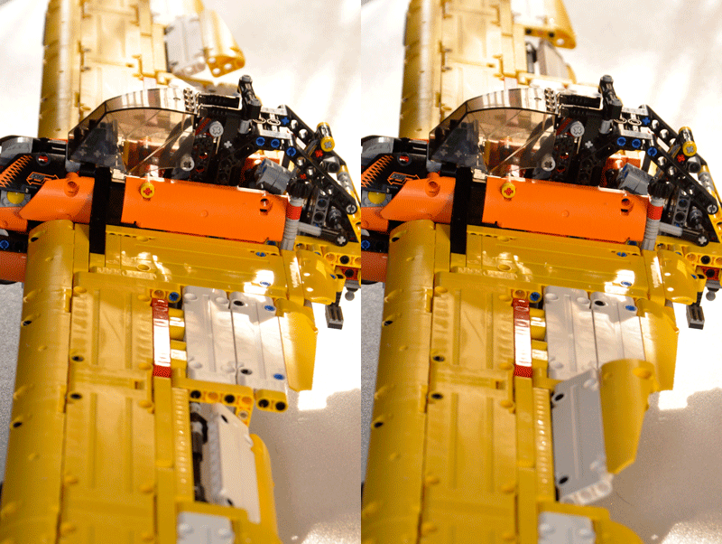
AILERONS
Ailerons control roll about the longitudinal axis. The ailerons are attached to the outboard trailing edge of each wing and move in the opposite direction from each other. In the model ailerons are connected by axels to a control stick. Moving the control stick to the right causes the right aileron to deflect upward and the left aileron to deflect downward. The increased lift on the left wing and the decreased lift on the right wing causes the airplane to roll in the longitudinal axe ascending the left wing and descending the right wing. Inversely, moving the control stick to left causes an inverse effect.


RUDDER
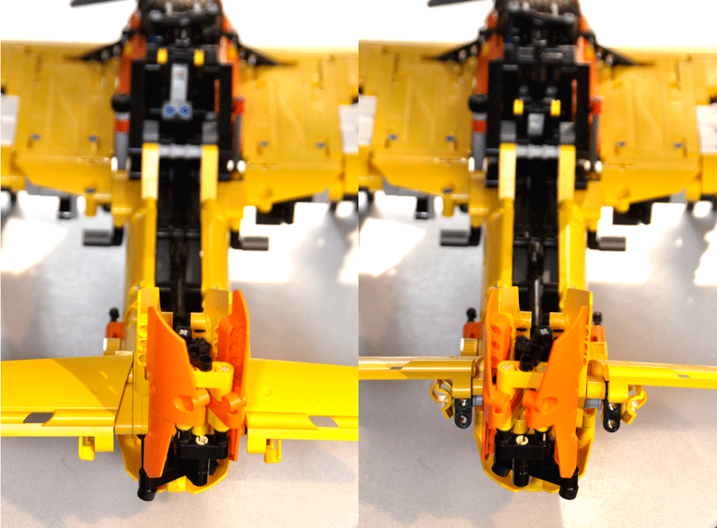
The rudder controls movement of the aircraft about its vertical axis. This motion is called yaw. Like the other primary control surfaces, the rudder is a movable surface hinged to a fixed surface, in this case to the vertical stabilizer, or fin. Moving the left or right rudder pedal controls the rudder.
When the rudder is deflected into the airflow, a horizontal force is exerted in the opposite direction. By pushing the left pedal, the rudder moves left. This alters the airflow around the vertical stabilizer/rudder, and creates a sideward lift that moves the tail to the right and yaws the nose of the airplane to the left. Rudder effectiveness increases with speed; therefore, large deflections at low speeds and small deflections at high speeds may be required to provide the desired reaction.
With the rudder, pedals also serve to control the directional wheel enabling airplane driving in earth.
In this model the rudder has to be moved by the fingers. So, it's positioned in the upper part of the model, enabling the manual control.

ELEVATOR
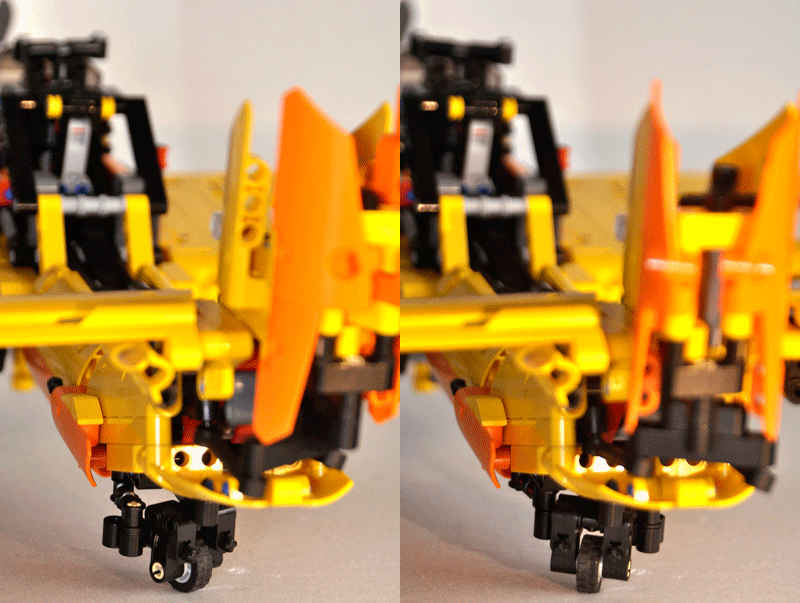
The elevator controls pitch about the lateral axis. The elevator is connected to the control column in the flight deck by a series of mechanical linkages. Aft movement of the control column deflects the trailing edge of the elevator surface up.
The up-elevator position decreases the camber of the elevator and creates a downward aerodynamic force, which is greater than the normal tail-down force that exists in straight-and- level flight. The overall effect causes the tail of the aircraft to move down and the nose to pitch up. The pitching moment occurs about the centre of gravity (CG). The strength of the pitching moment is determined by the distance between the CG and the horizontal tail surface, as well as by the aerodynamic effectiveness of the horizontal tail surface. Moving the control column forward has the opposite effect. In this case more lift on the horizontal stabilizer/elevator is created. This moves the tail upward and pitches the nose down. Again, the pitching moment occurs about the CG.
In the animated picture we can see the simultaneous movement of the rudder and the elevator.
Observe that due to the lack of non specular beams with bows (panels), some design licences have been taken. The rudder is made with symmetrical panels and the elevator is mono-block without horizontal stabilizer.
PRIMARY CONTROL SURFACES
As in any airplane you can find three primary control surfaces: ailerons, elevator and rudder.
The movement of this control surfaces determines the airplane stability in each of the 3D spatial axis.


